
It's an Enigma
November 2018
To those only casually acquainted with its story, the Enigma machine is perceived as being a highly secret German cipher machine whose code was broken by brilliant and eccentric British cryptanalysts during the dark days of World War II. While this perception is mostly accurate, it is considerably incomplete. The story of the Enigma machine is fascinating and complex, starting well before World War II and stretching across Europe and the Atlantic and involving international intrigue, spies, high seas adventure and...........patents. In an odd twist of irony, a number of patents were issued for the supposedly secret Enigma machine. Odder still, one of these patents was a British patent that disclosed a secret of the Enigma machine that initially prevented British cryptanalysts from breaking the Enigma code. Read on to learn more. Its a Patently Interesting Story!
Initially, a common misperception must be dispelled. The Enigma machine was not a single machine. Enigma was a brand name for a line of cipher machines sold by a succession of German companies. Indeed, the Enigma logo, shown above, was used in the sales and marketing of the machine. Interestingly, the Enigma logo is currently a registered trademark in the European Union for electronic cigarettes. In addition, an attempt was made by another company in the U.S. to register the Enigma logo for clothing. So, even today, the Enigma brand is perceived to have value.
Initially, a common misperception must be dispelled. The Enigma machine was not a single machine. Enigma was a brand name for a line of cipher machines sold by a succession of German companies. Indeed, the Enigma logo, shown above, was used in the sales and marketing of the machine. Interestingly, the Enigma logo is currently a registered trademark in the European Union for electronic cigarettes. In addition, an attempt was made by another company in the U.S. to register the Enigma logo for clothing. So, even today, the Enigma brand is perceived to have value.
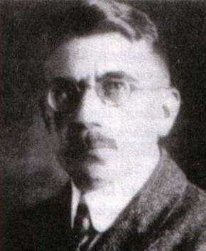 Arthur Scherbius
The story of the Enigma machine begins with Arthur Scherbius, a German electrical engineer who invented and filed a patent application for a rotor-based cipher machine on February 23, 1918. Seven years later, on July 8, 1925, the patent application issued as German patent DE416219. While his patent application was pending in the German Patent Office, Scherbius began building and marketing the cipher machine under the trademark "Enigma". Through his company, Chiffriermaschinen AG, Scherbius marketed the Enigma machine to business and industry, as well as to the German Army (the Reichswehr, which later became the Wehrmacht). Initially, the German Army was not interested in the Enigma machine, but then later changed their mind. The model that caught the German Army's attention was the Enigma D, which came out in 1926 and formed the basis for all subsequent Enigma machines.
At the request of the German Army, the Enigma D was modified to include several features that were not to be part of the commercial version. The most important of these modifications was the plugboard which was formally introduced in 1932. In that same year, the German Army claimed exclusive rights to the Enigma machine and further commercial sales of the machine had to be approved by them. The military version of Enigma D became known as Enigma I.
At the request of the German Army, the Enigma D was modified to include several features that were not to be part of the commercial version. The most important of these modifications was the plugboard which was formally introduced in 1932. In that same year, the German Army claimed exclusive rights to the Enigma machine and further commercial sales of the machine had to be approved by them. The military version of Enigma D became known as Enigma I.
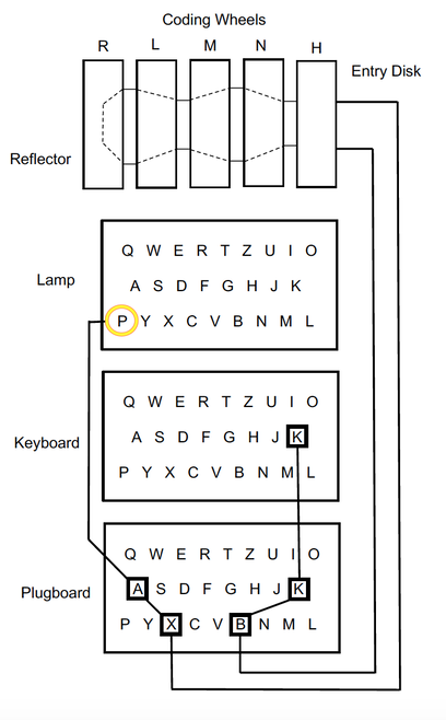 Simple schematic of the Enigma I
The Construction of the Enigma I
The Enigma I had a keyboard, a plugboard, an entry disk (H), three rotatable coding wheels (L,M,N), a reflector (R) and a lamp board, all of which were mounted inside a wooden housing. A battery supplied current to the circuit containing the foregoing components.
The keyboard had the same key arrangement as a standard German typewriter, which is slightly different than the familiar QWERTY typewriter. In a German typewriter, the Z is moved between the T and U to facilitate typing the frequently-used German digraphs TZ and ZU. In addition, the L, Y and P are moved to the bottom row.The plugboard was connected to the keyboard
The entry disk was fixed in position and did not rotate. It had opposing right and left faces, with each face having 26 electrical contacts. Inside the entry disk, the contacts on the opposing faces were wired together to make electrical connections. The contacts on the right face were electrically connected to the plugboard, which, in turn, was electrically connected to the keyboard and the lamp board. Like the entry disk, the reflector was fixed in position and did not rotate. It had a single face with 26 raised electrical contacts. Inside the reflector, pairs of the contacts were wired together. For example, the "A" contact could be wired to the "G" contact. The reflector allowed both encryption and decryption with the same machine setting and wiring.
Each coding wheel had a rotatable outer ring and opposing right and left faces, with each face having 26 raised electrical contacts. Inside the wheel, the contacts were wired together to make an electrical connection. The outer ring was marked with the 26 letters of the alphabet to provide a letter designation for each contact. Since the ring was rotatable, the letters for the contacts could be changed. The internal wiring of a coding wheel was asymmetric such that, for example, a contact on the right face designated by the letter "B" could be electrically connected to a contact on the left face designated by the letter "R".
The coding wheels were rotatably mounted inside the housing in a side-by-side manner such that the contacts on adjacent faces of the coding wheels were touching each other. In addition, the contacts on the right face of the rightmost coding wheel touched the contacts on the left face of the entry disk. Also, the contacts on the left face of the leftmost coding wheel touched the contacts on the right face of the reflector.
The coding wheels could be removed from the housing and rearranged. In addition, the coding wheels could be substituted with other coding wheels having different wiring, respectively. The coding wheels were also geared such that when a letter was typed on the keyboard, the rightmost coding wheel would rotate one contact postion (1/26th of a revolution). When the rightmost coding wheel made a complete revolution (after 26 position changes), the middle coding wheel would rotate one position. The leftmost coding wheel would, in turn, rotate one position after the middle coding wheel made one complete revolution.
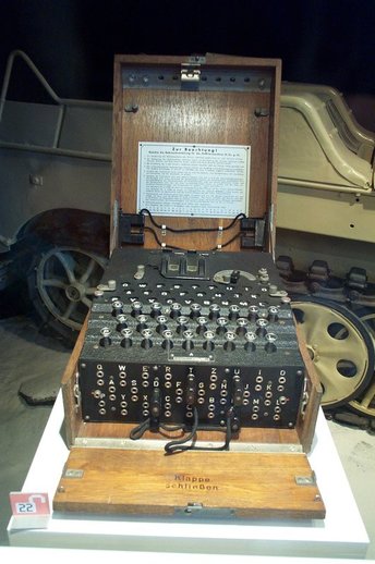 The Enigma machine (photo by LittleJoe)
The plugboard was connected between the keyboard and the entry disk, with each letter of the plugboard having a first jack normally connected to the keyboard and a second jack normally connected to the entry disk. Cables were provided for making letter substitutions. For example, if one end of a cable was connected to the second jack of the letter "K" and the other end of the cable was connected to the first jack of the letter "B", the letter "K" would be disconnected from the entry disk and the letter "B" would be disconnected from the keyboard; however, the letter "K" would be connected to the letter "B". Thus, if a "K" was typed on the keyboard, the plugboard would send a "B" to the entry disk, i.e., the plugboard substituted a "B" for a "K". Anywhere from 0 to 13 cables could be used to make substitutions on the plugboard. In the early years, only six cables were used, whereas in later years 10 cables were used.
The Operation of the Enigma I
In order to create an encrypted message using the Enigma machine, a transmitting operator woud type a message in plaintext on the keyboard, one letter at a time. When a key for a letter was depressed, an electrical signal would be transmitted from the keyboard, through the plugboard, into the entry disk, through the coding wheels, into the reflector (where it changed direction), then back through the coding wheels and the entry disk, into the plug board and then to the lamp board, where it lit up a lamp for a particular letter. The letter to which the signal pertained was repeatedly substituted as it traveled through the coding wheels, etc. to the lampboard. In the schematic (shown to the left), depressing the letter "K" on the keyboard would result in the light for the letter "P" to illuminate. In between, the letter to which the signal pertained was repeatedly substituted. For example, the plugboard substituted the letter "B" for the letter "K".
For each letter of the plaintext typed into the keyboard, the transmitting operator would write down the letter of the lamp that lit up in response. The resulting collection of letters from the lighted lamps would be the ciphertext that would then be transmitted by telegraph or other means to a receiving operator. For example, the plaintext typed into the keyboard may be "KITCHEN" and the resulting ciphertext may be "PTSLZOA", which was then transmitted to the receiving operator. After receiving the ciphertext, the receiving operator would type the letters "PTSZOA" into their keyboard and would note the letters for the lamps that were illuminated in response thereto. Assuming that the Enigma machines of the two operators had the same settings (discussed below), the illuminated letters displayed at the receiving operator's Enigma machine would be "KITCHEN". In this regard, the Enigma machine, through the operation of the reflector, both enciphered and deciphered.
In order for two enigma machines to encipher and decipher a message as described above, the two machines had to have the same settings. This was achieved through the use of a message key and a daily key. The daily key provided the order of the coding wheels, the plugboard setting, the ring settings of the coding wheels and a ground setting, which was the initial settings of the coding wheels for the message key. The message key was the settings for the coding wheels for a particular message.
Daily keys for an entire month were listed in a printed table that was distributed to Enigma operators. The message key was enciphered and transmitted at the beginning of each message and, as it turned out, was the achilles heel of the Enigma machine, or rather its use.
The message key was left to the discretion of a transmitting operator and consisted of three letters that were repeated. So, for example, if a message key was RTZ, the transmitting operator would encipher plaintext RTZRTZ to produce ciphertext that may be PHJKOM and then send the cipher text to the receiving operator, followed by the actual message.
Possible Settings
With the above-described construction and operation, the Enigma Machine had more than 1.06 X 10 to the 16
possible settings. This number is derived from the fact that each coding wheel had 26 possible positions and, thus, 3 coding wheels had 263or 17,576 possible settings. Since the coding wheels could be rearranged, there were 6 possible arrangements of the coding wheels, bringing the total number of possible settings to 6 X 17,576 or 105,456. The plugboard then multiplied this number enormously. If the number of cables used was from zero to 6, the number of possible settings was 100,391,791,500 X 105,456 or 1.06 X 10 to the 16 possible settings.
Even more mind numbing is the fact that the 1.06 X 10 to the 16 possible settings calculated above assumes that the internal wiring of the entry disk, the reflector and the coding wheels was known and that it was known that a maximum of six cables was being used!
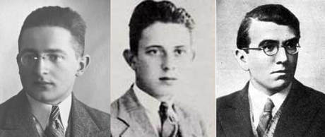 Rejewski, Rozycki and Zygalski
The Breaking of the Enigma System
Contrary to popular belief, the first people to break the code of the Enigma I were not British cryptographers, but instead, were Polish mathematicians. Working in the Polish Cypher Bureau, mathematicians Marian Rejewski, Jerzy Rozycki and Henryk Zygalski broke the code of the Enigma I in early 1933. Rejewski did most of the initial work, which is mainly discussed herein.
At first, the only tools available to Rejewski were intercepted German messages and a commercial Enigma D, which gave Rejewski a basic understanding of how the Enigma I worked. After reviewing several months worth of intercepted German messages, Rejewski determined that the Germans were using an encrypted message key that was sent twice at the beginning of each message. Rejewski recognized this procedure as being a flaw that could be exploited, both with regard to deciphering the message key and determining the wiring of the individual coding wheels.
The Message Key
With regard to deciphering the message key, Rejewski would collect message keys for a day. For each message key, Rejewski would correlate the first letter with the fourth letter in a table AD, with the first letter being positioned in a top row and the fourth letter being positioned in the same column in a bottom row. Rejewski would do the same for the second and fifth letters in a table BE and for the third and sixth letters in a table CF. An example of an AD table is shown below:
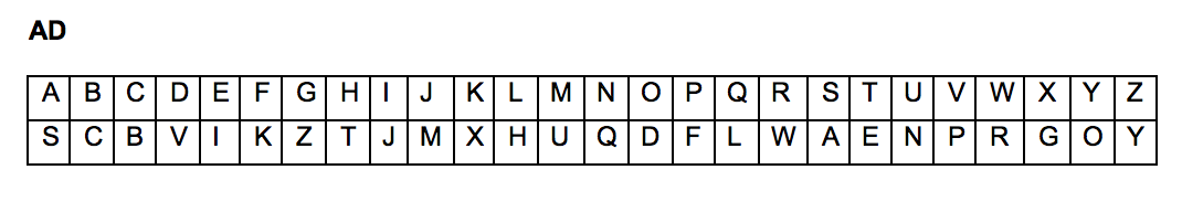
Each day, cycles AD, BE and CF were identified from message keys received during the day, using the tables AD, BE and CF, respectively. In each cycle, the first letter would be the first letter of a message key, as well as a top row letter. The second letter would be the bottom row letter corresponding to the first letter in the top row, the third letter would be the bottom row letter corresponding to the second letter in the top row and so on, until the corresponding bottom row letter was the same as the first letter, at which point the cycle would terminate. For example, using the above AD table for a first message key "dmqvbn", the first AD cycle would be "dvpfkxgzyo". From subsequent message keys, additional AD cycles would be identified. In a similar manner, BE and CF cycles would also be identified. An example of AD, BE and CF cycles is shown below:
AD= (dvpfkxgzyo)(eijmunqlht)(bc)(rw)(a)(s)
BE= (blfqveoum)(hjpswizrn)(axt)(cgy)(d)(k)
CF= (abviktjgfcqny)(duzrehlxwpsmo)
Rejewski determined that, although the plugboard setting affected the letters that were present in the different cycles, it did not affect the lengths of the cycles. Indeed, the lengths of the different cycles were independent of the plugboard setting. Moreover, the length pattern of the three sets of cycles, AD, BE and CF was a unique fingerprint for a particular coding wheel setting. In effect, the cycle fingerprints eliminated the need to consider the plugboard when determining the coding wheel setting. Thus, instead of searching through 1.06 X 10 to the 16 possible coding wheel settings, only 105,456 fingerprints had to be searched to determine the coding wheel settings, i.e., to decipher the message key.
At first Rejewski relied on knowledge of human behavior and several mathematical theorems he had developed to simplify the search through the 105,456 fingerprints. For example, he assumed that Enigma operators would often use simple message keys, such as AAA, BBB, or CCC, which turned out to be correct. Later, however, Rejewski and the other Polish mathematicians constructed an electrical machine they called a Cyclometer that used Enigma-type coding wheel to simplify the search. With the aid of the Cyclometer, the Polish mathematicians were able to decipher a message key in less than twenty minutes.
The Wiring of the Coding Wheels
The double transmittal of the encrypted message key also provided Rejewski with six permutations (one for each letter of the encrypted message key) that could be transformed into six equations (A-F):
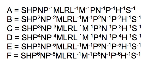
In the foregoing equations, S was a permutation for the plugboard, H was a permutation for the entry disk, N was a permutation for the wiring of the rightmost coding wheel, M was a permutation for the wiring of the middle coding wheel and L was a permutation for the wiring of the leftmost coding wheel. Since the rightmost coding wheel N rotated one position after each letter typed, a permutation P was added to account for this feature.
In late 1932, the Polish mathematicians fortuitously received information about the Enigma I from the French, who, in turn, received it from a German spy by the name of Hans Thilo Schmidt. The information included two tables of daily keys for September and October of 1932. Using this information, together with some mathematical manipulation and guessing, the Polish mathematicians were able to greatly simplify the above equations to solve for the wiring of the rightmost drum (permutation N). The simplification resulted in only four equations with a single unknown: NPN-1, which was solvable. Unfortunately, solving the simplified equations yielded results that were clearly incorrect. After some deliberation, Rejewski suspected that their guessing had been wrong.
In order to obtain the simplified equations, Rejewski had guessed that the wiring of the entry disk was the same in the Enigma I as in the commercial Enigma D, which was in their possession. The wiring of the entry disk in the Enigma D had the keys of the keyboard connected, in the order they appeared on the keyboard, to the contacts of the entry disk in alphabetical order. In other words, the entry disk converted QWERT, etc. of the keyboard to ABCDE, etc. If the entry disk was not wired in this manner, how was it wired?
A Red Herring
The setback with the wiring of the entry disk was disheartening and almost resulted in the abandonment of the Polish decipherment project. Luckily, Rejewski made another guess that turned out to be correct. Rejewski guessed that the successive contacts of the entry disk were simply connected to the keyboard in alphabetical order, i.e., a to a, b to b, c to c, etc. In other words, the entry disk was merely a pass-through that had no effect on the operation of the Enigma I. It was a red herring!
With Rejewski's second, correct guess about the wiring of the entry disk, the Polish mathematicians were able to determine the wiring of the rightmost drum and then the wiring of the other two drums, using the daily keys for September and October of 1932. Later, the Polish mathematicians worked out a method for determining the daily codes. They had succeeded in breaking the code of the Enigma I and were able to decipher intercepted German messages.
From the period of 1932 through 1939, the Germans continually changed the Enigma I and its operation, such as increasing the number of cables for the plugboard, increasing the number of available coding wheels to five, and changing the protocol for transmitting the message key. The Polish mathematicians were mostly able to keep up with these changes, but with increasing difficulty and less efficiency. By July of 1939, the Poles were running out of resources and knew that war was approaching, so they met with British intelligence in that month and gave them all of their decipherment work on the Enigma I.
As it turns out, at the time of their meeting with the Poles, British intelligence had not gotten very far in breaking the code of the Enigma I. Apparently, the British had taken a different approach in their decipherment work and had started with the entry disk, which had stumped them. During their meeting with the Poles, the first piece of informationn the British requested was the wiring of the entry disk. When they found it was nothing but a red herring, they were furious. To make matters worse, the pass-through nature of the entry disk was clearly shown in British patent GB231502 that Chiffriermaschinen AG had obtained in 1925. The British cryptologists had reviewed GB231502 and saw the wiring of the entry disk, but dismissed it as being too obvious.
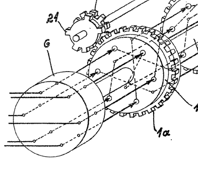
Schematic of the Entry Disk from GB231502